 Marten's
Tech Tip No 2
Marten's
Tech Tip No 2
Renault 5 CV Drive Shaft Joint.
The Haynes Manual is not very helpful when it comes to endeavouring to fit new rubber bellows units to your drive shafts. Dismantling is fine and the star cage can be removed as described, so long as you give the screwdriver (which needs to be fairly sharp) a sharp tap with a small hammer.
Clean out the hollow ends of the yoke and bell, you will need to be able to see what you are doing come re-assembly time.
A cone for fitting the bellows can be made from a food tin, a baked bean
tin will be big enough but you can use larger tins if you want a slower, longer
taper. Not too long or it will collapse, hence the strange shape of the cones
shown in the Haynes manual. Cut the ends off the tin and radius corners and
remove sharp edges.
Make one edge slightly bent so that it does not form a sharp edge when rolled.
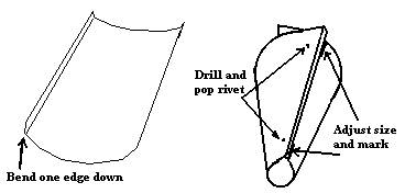
Roll the tin into a cone and ensure that the small end will admit the small diameter end of the bellows and mark the position of the edges. Check that the large end just fits over the taper on the yoke but does not quite reach the parallel surface, mark the edges.
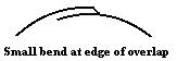
Holding the tin in its conical form, using first one end then the other,
position the tin at the marks and drill a hole for a pop-rivet near each end.
Making sure that the tin lies flat along its long edge. Pop-rivet the two
ends then drill how ever many holes for further rivets, depending on how long
you are making it, and rivet these.
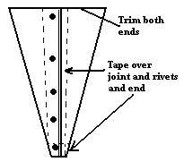
Checking that the ends still fit the bellows and the yoke, trim the edges
tidy at each end.
I suggest taping the small diameter end of the metal cone too, just in case
you slip when trying to fit the bellows. You don't want to slice your hand
on the edge of the tin.
Scotch tape over the rivet heads and straight edge and rub a small amount
of grease over it.
Using engine oil lubricate the interior of the small diameter end of the bellows. Try not to get on oil on the outside, or clean it off if you do, to enable a firm grip.
Cut two pieces of wood, about an inch to an inch and a half wide by about three eighths thick and about nine inches long and ensure that the ends are not splintery.
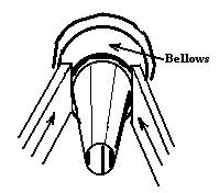
With the shaft and yoke held firmly in a vice position the small end of the
bellows on the cone and the cone against the yoke. (Don't overlook the point
that you want the small end on first.)
Push the bellows as far up the cone as you can by hand then push the large
end of the bellows over the small end doubling it back over the yoke.
With a piece of the timber in either hand push against the inside of the bellows,
close to the small diameter end, first one side then the other until the bellows
finally slide onto the parallel outer of the yoke.
The bellows will now slide easily off the inner end and it can be slid along
the shaft and the bellows turned right way out again.
Now for that re-fitting the yoke and bell housing, that the Haynes book
does nowhere near enough to explain, and this is where cleaning out the
yoke and bell will be advantageous.
Clamp the outer shaft vertically in a vice, using soft jaws in order not
to harm the shaft, bell uppermost.
Push the rollers on the spider towards the centre and position the starplate
with the prongs midway between each shaft and the ends equal distances from
the wall of the bell. (If you did not clean the Moly grease out this is
where it gets very difficult to keep an eye on just where that starplate
ends up.)
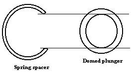
Fit the spring into the recess in the spider centre and then the dome-head
plunger BUT NOT the spring spacer.
(I wasted two hours trying to re-assemble my unit because Haynes did not
mention this.)
Offer up the shaft with the yoke keeping it vertical and the bellows towards
the inner joint, out of the way.
Slowly slide the yoke over the spider ensuring that the rollers all engage
in the slots and try not to dislodge that starplate.
Still keeping the shaft vertical, thrust quickly down as far as it will
go. Hopefully you will hear the very satisfying sound of a slight 'click'
as at least two of the starplate ends engage. (This sound will be deadened
if the grease is left in.)
Tilt the driveshaft all three ways to inspect the slots. Any starplate ends
not yet fully engaged may be encouraged into position by tilting the shaft
in that direction and repeating the sharp thrust down.
If you do not engage any starplate ends, or only one, you will have to remove
the shaft and reposition the starplate and try, try again.
(Emergency only: If you cannot get it to engage at all try my method of
grinding a VERY SMALL extra lead-in slope on the very bottom outer edge
of the yoke. And make sure that you clean it free of grit immaculately.)
Once all three ends of the starplate are engaged and firmly in their positions
THEN you can add that strange spacer. It is only three quarters circumference
and it was this that finally got it into my head that it had to be so for
a reason, and that was to allow it to be slipped in between two arms of
the yoke, slid under the head of the dome plunger then nudged home with
a screwdriver blade. Piece of cake! Eventually!
(Note from webmaster..Thankyou Marten for this tip, Ive always shied away
from the task as the one time i tried i landed up wth ball bearings all
over the place and oil over the garage floor.)
Had a report from Mark Kuzniar on his experiance:
Mark,
used your advice to split drive shaft, fit boot and re-join shaft, aided
by
many four lettered words, cups of tea and cigarettes. However, the opposite
side went a few weeks later. Unwilling to go through the process again I
sought another option. Did you know that there is a stretchy polymeric CV
boot that can be purchased (Gearbox in Melton Mowbray have them in stock
and
free fitting tool hire)? These are heated in hot water, and are then pliant
enough to be stretched over the whole shaft, thus eliminating the need to
break the joint. The quality of the parts are good and they avoid the
problems associated with the split style boot.
Hope this may be of use to some body.
Regards,
Mark Kuzniar
![]()